This CPD, sponsored by RIW, will outline the additional considerations that designers should be aware of to ensure the most efficient and robust waterproofing system is selected for their project.
CPD CREDITS: 60 MINUTES
DEADLINE: 18 DECEMBER 2018
For more information about Assemble Media Group’s CPD distance-learning programme, click here

INTRODUCTION
When considering existing basements, multi-level basements, basements in high water tables, basements with complex foundations, basements constructed inside permanent works or basements constructed against adjacent properties, there are many different challenges which make every basement unique. This CPD will outline the additional considerations that designers should be aware of to ensure the most efficient and robust waterproofing system is selected for their project.
Different types of waterproofing protection as defined in BS 8102:2009
There are many different waterproofing products available in the marketplace. Waterproofing systems can be applied in a number of ways and located in a number of different positions against the structure. In order to make sense of all the available products the BS 8102:2009 document classifies each waterproofing product as either a Type A, Type B or Type C method of waterproofing protection.
Type A – Barrier Protection
This is a continuous, impervious barrier applied to the outside or inside face of the basement structure which stops groundwater passing through it and into the structure. The Type A classification includes many different varied products and is the broadest category of waterproofing protection. Type A barriers could include liquid applied membranes, bonded sheet membranes, geosynthetic clay liners, cementitious slurries, mastic asphalt membranes or cementitious multi-coat render systems.
Within each of these sub-categories there are multiple product types, each potentially with a different method of application and form as well as different set of advantages and disadvantages. These products are designed to perform well in the very specific application they have been designed for, matching the correct product to any given specific application is essential to ensure the product is placed in the correct environment.
Although there are a limited number of Type A barriers which can resist mechanical damage and UV exposure, in almost all circumstances the Type A system should be protected and ‘hidden’ by backfill or finishes.
Type B – Structurally Integral Protection
In this approach the basement structure is formed from a material which is itself inherently water resistant; this may typically be well-designed reinforced concrete but may also include steel construction (e.g. steel sheet piling). Waterproofing admixtures may also be incorporated into the concrete mix to further reduce the crack width, permeability or shrinkage and thereby the water/vapour transmission rates through the basement structure. Vulnerable locations in construction posing risk for seepage, such as penetrations and joints should be addressed by design and joint protection systems (e.g. waterstops, sealants).
Type C – Drained Protection
While Types A and B methods of protection seek to halt water ingress into the structure, a Type C method of protection accepts that some water or water vapour may still gain entry into the basement structure. This ingress is ‘managed’ typically by providing a drainage void around the inside face of the basement structure which directs all water ingress to a dedicated drainage discharge system which removes the water from the basement. The drainage void around the inside face of the basement structure is often formed by installing a studded plastic drainage sheet, onto which subsequent basement floor and wall build-up can be installed. These studded plastic sheets are not designed to be left exposed or trafficked, instead they should be ‘hidden’ and protected from UV exposure and mechanical damage by subsequent installation of floor screed and wall linings.
Combined protection
In certain circumstances the BS 8102:2009 standard recommends considering combining two or more forms of waterproofing systems (e.g. Type A and B or Type B and C etc.). In addition to the guidance in the BS 8102:2009, some building warranty providers will also have additional requirements for projects where their warranty products are sought. The design team should engage with any such warranty providers at the earliest opportunity to ensure that they can meet any additional requirements. Such warranty providers include NHBC and LABC for example.
Wall and floor build-up, repairability and the impact on waterproofing system choice
The presence or absence of wall and floor build-up will also have an impact on the most efficient system of waterproofing.
Example 1
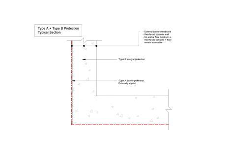
For basement structures where no floor or wall finishes are proposed (e.g. basement car parking) an efficient system of waterproofing could be a Type A membrane applied to the outer face of the structure and/or a Type B method of protection incorporating an optional water tight concrete admixture in the reinforced concrete.
Benefits
Such methods of protection mean that additional wall or floor build-up are not required to protect the waterproofing and more importantly, should there be any water ingress into the structure, the substrate remains accessible for repair.
This method of waterproofing is generally a faster application process as it does not require the additional protective layers (i.e. wall build-up, floor screed etc.). Depending on the choice of technology, Type A systems may have a full bond and minimize water migration by limiting and localizing the leaks; they can be suitable for use in alkaline and harsh conditions and may be used as gas protection.
Limitations & Reparability
In the example shown above once a leak has occurred it is often impractical or impossible to gain access to the externally applied Type A barrier membrane. Therefore the inside face of the Type B structure is treated to halt water ingress. Typically there are two different approaches when repairing the internal face of a leaking concrete structure:
- Resin Injection
- Cement based, mortars and slurries
In either case it will be necessary to gain access to the inside face of the concrete wall to identify the location of the leak before any repair works can be attempted. For this reason if the above method of protection is provided in a building where finishes and wall/floor build-ups are proposed, intrusive works will be necessary to remove wall linings and floor build-up to locate and then treat the leaking area. This should be a consideration for the designer – it is likely there will be considerable disruption to the client and the use of the building during such works.
Example 2
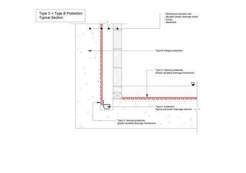
Let us take a habitable dwelling with two storeys of basement for which a basement structure with ‘combined protection’ is a requirement from the warranty provider. A wall build-up of insulation and blockwork and floor build-up of insulation and screed are proposed in all basement areas.
In this instance a Type C method of protection could be considered an efficient system because both the horizontal and vertical application of the studded plastic sheet will be protected from mechanical damage and trafficking.
Benefits, Maintenance & Reparability
A Type C system accepts that some water ingress will make its way into the structure. This water is taken to a collection point (typically a perimeter drainage channel) and then discharged out of the building by gravity-fed drainage where appropriate or by mechanical means.
In order to prevent blockages in the Type C drainage system, inspection points should be located periodically along the length of the perimeter drainage channel.
The Type C system should remain accessible for cleaning and maintenance throughout its life, which could be achieved by a number of access points located regularly along the collection and discharge pipework. If designed and installed properly the maintenance of the system will prevent water ingress issues, including intrusive fixing works (removing finishes, wall linings etc.).
Limitations
Type C methods of protection are generally only designed to accept ’seepage’ of water or water vapour through the structure. Therefore before a Type C method of protection can be considered it will be necessary to ensure there is continuous structure onto which the Type C system is installed. In high risk solutions it may also be necessary to restrict water ingress into the Type C system further by providing combined protection (e.g. with Type A or Type B methods of protection).
Type C method of protection must be covered and protected from mechanical damage and trafficking, typically by blockwork or other wall linings (vertical) and floor screeds (horizontal); this can add cost and time to the build if these layers had not already been proposed. Type C systems also decrease usable space. They also require pump maintenance and need careful evaluation of the water discharge point.
Drainage layouts for cavity drain systems
The perimeter drainage channel collects the water which has entered the Type C system. Current best-practice guidance suggests there should be a minimum of two ‘outlets’ from this perimeter drainage channel for basement arrangements with up to 100 linear metres of perimeter drainage channel. An additional ‘outlet’ should be considered every additional 50 linear metres of perimeter drainage channel (e.g. 110 linear metres = 3 x outlets whereas 160 linear metres = 4 outlets).
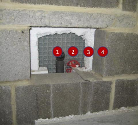
Inspection points should be located along the length of the perimeter drainage channel. These should be spaced at 12 metre centres. The precise location of the inspection points can be adjusted to suit the desired finish in that particular area (e.g. it may be desirable to locate an access point in a cupboard under the stairs rather than placing this in the middle of a living room).
Photograph of typical ‘Inspection Point’ pipework located behind blockwork wall. An access panel will eventually cover this space in the blockwork, to suit the architectural finish:
Structures with Multiple Occupancy
For below-ground structures with multiple occupancy (e.g. a row of terraced houses which all share the same retaining wall) it is necessary to develop a drainage and discharge strategy that enables each property owner to effectively maintain their own property.
This means that each individual property has outlets and inspection points to suit and that each property owner does not have to rely on each other to maintain a ‘shared’ drainage system.
How to take this module
Assemble Media Group’s CPD distance-learning programme is open to anyone seeking to develop their knowledge and skills. Each module also offers members of professional institutions an opportunity to earn between 30 and 90 minutes of credits towards their annual CPD requirement.
This article is accredited by the . To earn CPD credits, read the article and then click the link below to complete your details and answer the questions. You will receive your results instantly, and if all the questions are correctly answered, you will be able to download your CPD certificate straight away.
CPD CREDITS: 60 MINUTES
DEADLINE: 18 DECEMBER 2018
Privacy policy
Information you supply to Assemble Media Group Limited may be used for publication and also to provide you with information about our products or services in the form of direct marketing by email, telephone, fax or post. Information may also be made available to third parties. Assemble Media Group Limited may send updates about �ڶ����� CPD and other relevant Assemble Media Group Limited products and services. By providing your email address you consent to being contact by email, telephone, fax or post by Assemble Media Group Limited or other third parties. If at any time you no longer wish to receive anything from Assemble Media Group Limited or to have your data made available to third parties, contact the Data Protection Coordinator at building@building.co.uk. View our full privacy policy he








No comments yet